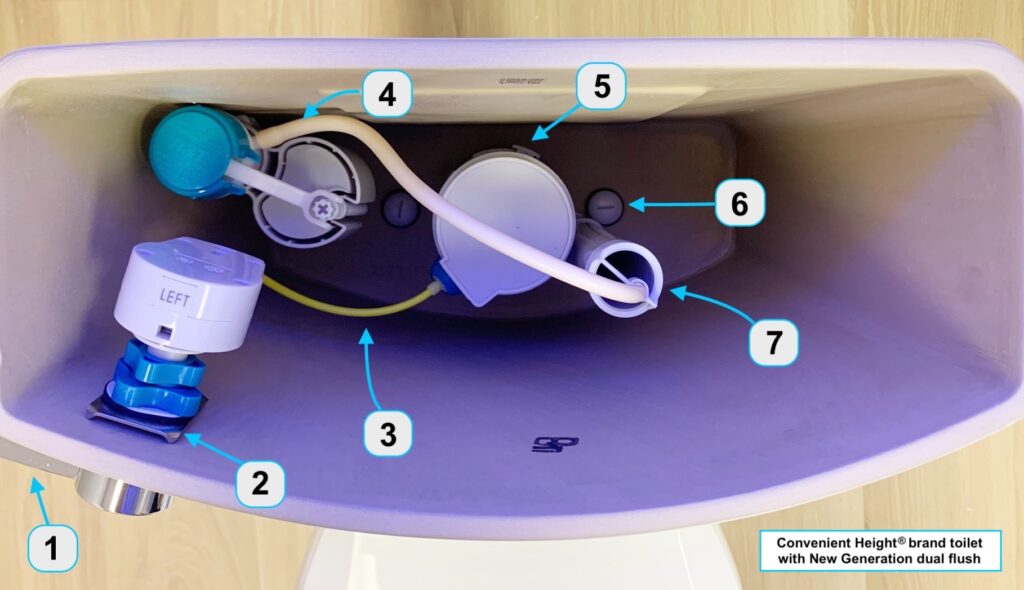
Toilet tank part install overview

Due to popular demand by our wonderful installer plumbers across the United States, we are starting to supply the printed copy of the supplemental Installed Flush Part Overview in addition to our install page online and printed instructions.
Installed Flush Part Overview
- (Element 1) Flush lever handle to allow two directional movement once connected to the actuator. Lever dual flush functions are: lift handle up for less water and press down for a full flush. Ensure the up/down motion of the handle as a lever metal key rod is inserted into the actuator. The handle remains horizontal once connected to the actuator.
- (Element 2) Shows small part placement lineup: large metal bracket direct to porcelain, followed by a rubber washer and a slim white washer. Tighten all three with the large blue spinner. Element 2 follows steps as described for Element 1.
- (Element 3) Yellow cord to remain minimally bent. Yellow cord housing protects a metal wire inside. Metal wire should move freely within its yellow protective housing when the flush lever handle is pressed up and down.
- (Element 4) The fill valve tube must remain clear of the fill valve float rising during water fill, and dropping during flush cycles. Continue positioning until parts do not interfere.
- (Element 5) Dual flush valve cylinder locks into the flush valve bracket. First, the bracket with overflow pipe is secured by tightening it underneath the tank, in the position as shown in Element 7. Then, insert and turn flush valve cylinder to lock into bracket.
- (Element 6) The tank to bowl connector bolt remaining visible ensures the valve bracket stays level. Visually the overflow tube should not block or interfere with the tank to bowl connector bolt (steps described in Element 5).
- (Element 7) Shows overflow tube positioning for no interference with the connector bolt.
- When completed, final tank part assembly view should match the image above. And we are here to help at ConvenientHeight.com/installation or call us (617) 419-0814
Continue Reading
Subscribe to Updates 


Leave Your Comment